Car Turning Indicator
5 in stock
Click Here to Download the Circuit Diagram of “Car Turning Indicator”
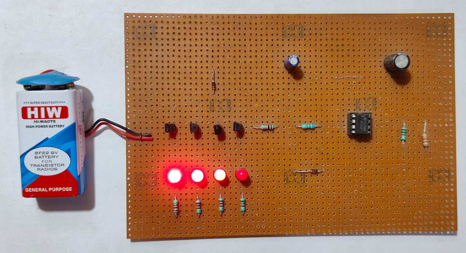
The Car Turning Indicator project provides visual signals to indicate a vehicle’s turning or lane change. Using a set of LEDs or bulbs and a control circuit, such as a relay or electronic flasher, the system activates the appropriate lights on the car. This project enhances road safety by making the vehicle’s intentions clear to other drivers.
₹295.00 ₹460.20 (Incl. GST)
5 in stock
Car Turning Indicator
A “Car Turning Indicator” mini project typically involves creating a circuit that mimics the turning indicator lights used in vehicles. Here’s an overview of how such a project might be approached:
Components Needed:
- 555 Timer IC: Used to generate the clock signal for the blinking indicator.
- Resistors: For setting the timing intervals with the 555 Timer.
- Capacitors: Used in conjunction with the resistors for timing.
- LEDs: Represent the indicator lights; typically, yellow or orange LEDs are used.
- Transistors: To drive the LEDs if the current requirement is higher.
- Switches: To simulate the turn signal lever in a car.
- Power Supply: A battery or DC power supply, typically 9V or 12V.
Circuit Explanation:
- 555 Timer IC: Configured in astable mode to produce a continuous square wave signal that alternates between high and low states. This square wave drives the LEDs to blink on and off, simulating a car’s turning indicator.
- LEDs: Connected to the output of the 555 Timer through a resistor. When the output is high, the LEDs light up, and when the output is low, the LEDs turn off.
- Switches: Two switches are used to simulate the left and right turn signals. When one switch is pressed, the corresponding set of LEDs (left or right) starts blinking.
How It Works:
- When you press the switch for the left turn, the 555 Timer circuit starts the blinking sequence for the left-side LEDs.
- Similarly, pressing the right turn switch starts the blinking sequence for the right-side LEDs.
- The rate of blinking can be adjusted by changing the resistor and capacitor values in the 555 Timer circuit.
Application:
This project is a simple yet effective way to learn about the 555 Timer IC, basic electronics, and the practical application of circuits in real-world scenarios like automotive lighting systems.
Further Enhancements:
- Use of Microcontroller: For more advanced control, you can replace the 555 Timer with a microcontroller like an Arduino, which can offer more precise control and additional features like adjustable blinking rates, hazard light simulation, etc.
- Sequential Indicators: Implementing sequential LED indicators where LEDs light up in a sequence, similar to modern car indicators.
This mini project is great for beginners to understand the basics of timing circuits and automotive electronics.
| Weight | 0.00 kg |
|---|---|
| Dimensions | 0.00 × 0.00 × 0.00 cm |


