
Astable Multivibrator using IC555
15 in stock
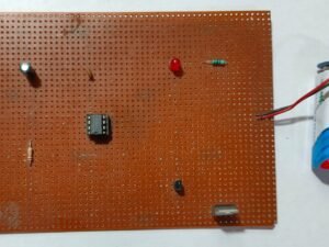
The Astable Multivibrator using IC 555 creates a continuous square wave output, functioning as an oscillator. Configured with resistors and capacitors, the 555 timer generates a periodic signal used for applications like blinking LEDs or generating clock pulses. This project demonstrates the timer’s capability to produce adjustable frequency waveforms.
₹295.00 ₹531.00 (Incl. GST)
15 in stock
Astable Multivibrator Using IC 555
The Astable Multivibrator using IC555 is a fundamental electronic circuit used to generate continuous square wave signals without the need for external triggering. By utilizing the IC 555 Timer, this circuit can create oscillations of specific frequency and duty cycle, which are useful for various applications such as signal generation, pulse width modulation, and clock pulses for digital circuits.
Components Needed
- IC 555 Timer: The central component for generating the square wave signal.
- Resistors: Typically, two resistors are used to set the timing parameters (e.g., 1kΩ and 10kΩ).
- Capacitor: A capacitor (e.g., 10µF) to define the frequency of oscillation.
- PCB (Printed Circuit Board): For a compact and durable assembly.
- Power Supply: 5V DC to power the circuit.
How It Works
In the astable mode, the IC 555 operates as a free-running oscillator. It continuously switches between high and low states, creating a square wave output. The frequency of oscillation and the duty cycle of the output waveform are determined by the values of the resistors and capacitor connected to the IC.
- Timing Resistors (R1 and R2): These resistors, connected between the supply voltage and the discharge pin of the IC, control the charge and discharge times of the capacitor.
- Timing Capacitor (C1): Connected between the discharge pin and ground, this capacitor charges and discharges according to the timing resistors, setting the frequency of the oscillation.
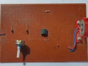
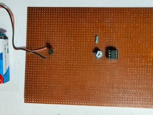
Assembly
To assemble the circuit, place the IC 555 and other components on a PCB. Connect the resistors and capacitor according to the astable mode configuration. Ensure proper power supply connections and secure all components.
The Astable Multivibrator Using IC 555 is a versatile circuit, providing a stable and adjustable frequency output, useful in a wide range of electronic applications.
| Weight | 0.00 kg |
|---|---|
| Dimensions | 0.00 × 0.00 × 0.00 cm |
Related products
-
B.Tech Diploma Mini Projects
DC Motor Speed Control
Click Here to Download the Circuit Diagram of “DC Motor Speed Control”
The DC Motor Speed Control project adjusts the speed of a DC motor using a variable resistor or Pulse Width Modulation (PWM) signal. By varying the voltage or duty cycle applied to the motor, you can control its rotational speed. This project demonstrates motor control techniques, providing practical experience in adjusting motor performance for various applications.
SKU: dc-motor-speed-control-project -
B.Tech Diploma Mini Projects
Temperature Indicator using LM35 and IC741
The Temperature Indicator using LM35 and IC741 project measures and displays temperature values. The LM35 temperature sensor provides an analog voltage proportional to the temperature, which is fed into the IC741 operational amplifier. The IC741 amplifies and processes the voltage signal, allowing it to be read on a display or analog meter. This project demonstrates analog temperature measurement and signal conditioning using commonly available electronic components.
SKU: temperature-indicator-using-lm35-and-ic741-project -
B.Tech Diploma Mini Projects
Dark Sensor Using LDR
Click Here to Download the Circuit Diagram of “Dark Sensor Using LDR”
The Dark Sensor using an LDR (Light Dependent Resistor) detects low light conditions to trigger an output action, such as turning on an LED or activating a relay. The LDR changes resistance based on ambient light levels, which is used to control the circuit, making it ideal for automatic lighting systems and light-sensitive applications.
SKU: dark-sensor-project -
B.Tech Diploma Mini Projects
IR Remote Tester
The IR Remote Tester project verifies the functionality of an infrared (IR) remote control. By using an IR receiver and a display or LED, this circuit detects and displays signals from the remote. When a button is pressed, the tester shows whether the remote is transmitting a signal, helping diagnose remote control issues.
SKU: ir-remote-tester-project