Half Wave Rectifier
2 in stock
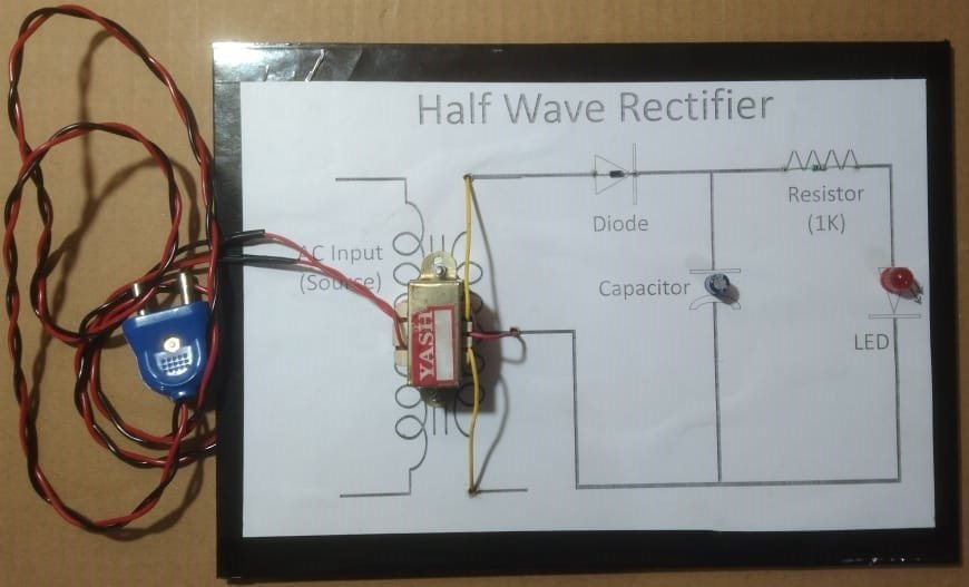
Click Here to Download the Circuit Diagram of “Half Wave Rectifier”
A half-wave rectifier converts AC voltage to DC voltage using a single diode. In this project, connect an AC voltage source to the input terminals of a diode, with the anode connected to the positive terminal of the AC source and the cathode to a load resistor. The diode allows current to pass only during the positive half of the AC cycle, blocking the negative half. The output across the load resistor will be a pulsating DC signal, representing only the positive half of the input AC waveform. This setup demonstrates the basic principle of rectification and provides insight into the function of diodes in power supplies.
₹442.50 ₹649.00 (Incl. GST)
2 in stock
Half Wave Rectifier Project
A half-wave rectifier is an electronic circuit designed to convert alternating current (AC) into direct current (DC) by allowing only one half-cycle of the AC voltage to pass through, effectively blocking the other half. This process is fundamental in power supply units and various electronic devices.
Components Used:
- Transformer: Steps down the high AC voltage to a lower, manageable level suitable for rectification.
- Diode: Allows current to flow in a single direction, facilitating the rectification process by permitting only the positive half-cycles of AC to pass through.
- Resistor: Limits the current flow within the circuit, protecting components from potential damage due to excessive current.
- Capacitor: Smooths the pulsating DC output by filtering out voltage ripples, resulting in a more stable DC voltage.
- LED (Light Emitting Diode): Acts as an indicator, illuminating when current flows through the circuit, thereby confirming the presence of output voltage.
Working Principle:
During the positive half-cycle of the AC input, the diode becomes forward-biased, allowing current to pass through the load resistor. Simultaneously, the capacitor charges up to the peak voltage. In the negative half-cycle, the diode is reverse-biased, blocking current flow. The charged capacitor then discharges through the load, providing a continuous DC output. The LED lights up during the positive half-cycle, indicating active current flow.
Applications:
- Signal Demodulation: Extracts the audio signal from modulated radio signals.
- Power Supply Circuits: Provides DC voltage for low-power devices and appliances.
- Pulse Generation Circuits: Generates DC pulses for timing and control applications.
Advantages:
- Simplicity: Comprises a straightforward design with minimal components, making it easy to construct and understand.
- Cost-Effective: Requires fewer components, leading to lower manufacturing costs.
Limitations:
- Inefficiency: Utilizes only half of the AC waveform, resulting in significant power loss and reduced efficiency.
- High Ripple Factor: Produces a pulsating DC output with substantial ripples, necessitating additional filtering for applications requiring smooth DC voltage.
- Low Output Voltage: Delivers a lower average output voltage compared to full-wave rectifiers.
Conclusion:
While half-wave rectifiers are suitable for simple, low-power applications due to their ease of implementation and cost-effectiveness, they are generally inadequate for powering sensitive electronic equipment. The inherent inefficiency and high ripple content limit their use in scenarios where a stable and smooth DC output is essential. In such cases, more efficient rectification methods, like full-wave rectifiers, are preferred.
| Weight | 0.00 kg |
|---|---|
| Dimensions | 0.00 × 0.00 × 0.00 cm |
You may also like…
-
B.Tech Diploma Mini Projects
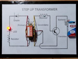
Step Up Transformer
A Step-Up Transformer increases voltage from a lower to a higher level by using two coils: the primary and secondary. The secondary coil has more turns, producing a higher output voltage. This project demonstrates its role in power transmission, reducing energy losses, and applications in electrical devices like microwaves and X-rays.
SKU: Step Up Transformer
Related products
-
B.Tech Diploma Mini Projects
Electronic Letter Box using IC 555
The Electronic Letter Box project automates mail detection and notification. It typically uses sensors (like infrared or magnetic) to detect when the letter box door is opened or when mail is inserted. The system can activate an alert, such as a buzzer or LED, to notify the owner of new mail. This project integrates sensor technology with electronic signaling to improve mail management and security.
SKU: electronic-letter-box-project -
B.Tech Diploma Mini Projects
Transistor as Switch
Click Here to Download the Circuit Diagram of “Transistor as Switch”
The Transistor as a Switch project demonstrates how a transistor can control a high-current load with a low-current signal. In this setup, the transistor acts as an electronic switch, using its ability to amplify current to turn a load on or off.
Components:
- NPN Transistor (e.g., BC547)
- Resistor (base resistor)
- Load (e.g., LED with current-limiting resistor)
- Power Supply
Working:
- Base Resistor: Connects the transistor’s base to a control signal (e.g., a microcontroller or a switch). This resistor limits the base current.
- Collector-Emitter Path: The load is connected between the collector of the transistor and the power supply. When the transistor is in the “on” state (saturated), current flows from the collector to the emitter, powering the load.
- Control Signal: Applying a small voltage to the base allows a larger current to flow from the collector to the emitter, thus switching the load on.
When the control signal is high, the transistor conducts, and the load is energized. When the control signal is low, the transistor stops conducting, and the load turns off. This simple yet effective project showcases the transistor’s utility in switching applications.
SKU: transistor-as-switch-project -
-
B.Tech Diploma Mini Projects
Zener Diode as Voltage Regulator
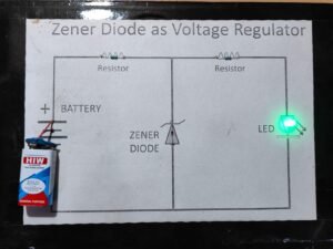
Click Here to Download the Circuit Diagram of “Zener Diode as Voltage Regulator”
The Zener Diode as a Voltage Regulator project involves using a Zener diode to maintain a stable output voltage across varying input voltages. The Zener diode operates in reverse breakdown mode, where it maintains a constant voltage (the Zener voltage) regardless of changes in input voltage or load conditions.
In this project, a Zener diode is connected in reverse bias across a load resistor. When the input voltage exceeds the Zener voltage, the diode starts conducting and clamps the output voltage to the Zener voltage. This configuration ensures a stable and regulated output voltage, making it ideal for powering sensitive electronic circuits. Proper heat dissipation and current limiting resistors are essential for optimal performance and reliability.
SKU: zener-diode-as-voltage-regulator-project