NOR Gate
5 in stock
Click Here to Download the Circuit Diagram of “NOR Gate”
Explore the NOR gate, a fundamental digital logic gate essential for constructing complex circuits and performing universal logical operations.
₹295.00 ₹413.00 (Incl. GST)
5 in stock
NOR Gate Mini Project
The NOR Gate Mini Project is an educational and straightforward project designed to teach beginners about digital logic gates. The NOR gate (NOT OR) is another fundamental logic gate used in digital electronics, similar to the NAND gate, and is also a universal gate. This means it can be used to create other logic gates, such as AND, OR, NOT, NAND, and XOR, by combining NOR gates in specific configurations.
This project introduces the basic functionality of a NOR gate, demonstrates its working using simple components, and provides a hands-on understanding of its practical applications in electronic circuits.
Key Components:
- NOR Gate IC (e.g., 7402 series): A popular IC that contains four NOR gates, making it ideal for basic experiments.
- Resistors and LEDs: LEDs are used to show the output states, while resistors limit the current flowing through the LEDs.
- Switches: Used to toggle the inputs between logic high (1) and low (0).
- Breadboard and Jumper Wires: For assembling the circuit without the need for soldering.
- Power Supply: To provide the necessary operating voltage (typically 5V for TTL logic gates).
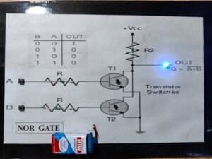
How the NOR Gate Works: The NOR gate operates as an OR gate followed by a NOT gate, which means it produces a high output (1) only when both inputs are low (0). If one or both inputs are high (1), the output will be low (0).
- Truth Table for NOR Gate:
| Input A | Input B | Output (A NOR B) |
|---|---|---|
| 0 | 0 | 1 |
| 0 | 1 | 0 |
| 1 | 0 | 0 |
| 1 | 1 | 0 |
Circuit Design:
- Set up the NOR Gate IC: Begin by connecting the power and ground pins of the NOR gate IC (like the 7402 series) to the breadboard’s power supply.
- Input Control: Connect two switches to control the inputs of the NOR gate. These will allow you to toggle between logic high (1) and logic low (0) for each input.
- Output Indicator: Attach an LED to the output pin of the NOR gate. The LED will light up when the output is high (1) and will remain off when the output is low (0).
- Experiment: Toggle the switches to simulate different input combinations and observe how the output changes based on the inputs. You can test all possible combinations of input A and B (both low, one low, one high, and both high).
Applications:
- Universal Gate: Since NOR is a universal gate, you can create any other logic gate (AND, OR, NOT, NAND, XOR) using only NOR gates. This project can be extended to build such logic gates and explore more complex circuits.
- Basic Digital Circuit Design: NOR gates are found in various digital circuits, such as memory units, flip-flops, and microprocessors, making this project foundational for more advanced studies.
- Training for Logic Design: Learning how NOR gates work prepares students to understand larger, more intricate logic systems.
Advantages:
- Simplicity: The project uses basic, low-cost components, making it perfect for beginners who want to understand the fundamentals of digital electronics.
- Expandability: Once familiar with the NOR gate, learners can easily expand the project to include more complex circuits involving combinations of NOR gates or other logic gates.
- Real-World Applications: NOR gates are extensively used in computing and digital systems. Understanding how they work provides insight into the operation of larger systems like microprocessors and digital storage devices.
Steps to Build the Project:
- Gather Components: Start by gathering all the necessary components, including the NOR gate IC (7402), resistors, LEDs, switches, breadboard, and jumper wires.
- Assemble the Circuit: Place the NOR gate IC on the breadboard and connect its power and ground pins. Wire up the input switches and output LED according to the NOR gate pinout.
- Test the Logic: Toggle the input switches and observe how the output LED responds. This will help you understand the behavior of the NOR gate for different input combinations.
- Expand the Project: After mastering the basic NOR gate circuit, try constructing other gates using NOR gates or combine multiple NOR gates to design more complex digital circuits.
Conclusion: The NOR Gate Mini Project offers a hands-on introduction to digital logic, particularly focusing on the NOR gate. This project is ideal for students, electronics hobbyists, or anyone interested in learning about basic digital circuits. By understanding how a NOR gate works, users can build on their knowledge to design more complex digital systems, which are the building blocks of computers, communication devices, and modern electronics.
| Weight | 0.00 kg |
|---|---|
| Dimensions | 0.00 × 0.00 × 0.00 cm |


