Wireless Power Transfer
1 in stock
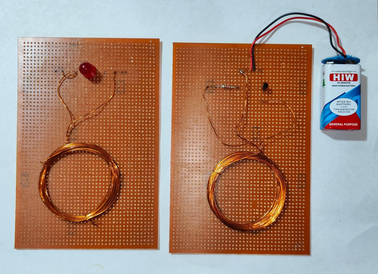
The Wireless Power Transfer Project explores the technology of transmitting electrical energy without physical connections. Utilizing principles such as electromagnetic induction or resonant inductive coupling, it demonstrates how power can be transferred between coils or circuits. This project is ideal for applications like wireless charging for devices, powering remote sensors, and advancing energy-efficient systems. It combines practical hands-on experimentation with fundamental electrical engineering concepts.
₹295.00 ₹531.00 (Incl. GST)
1 in stock
Wireless Power Transfer
Wireless power transfer (WPT) technology allows electrical energy to be transmitted from a power source to an electrical load without physical connections. This mini project demonstrates a basic WPT system using a simple transistor circuit.
Project Overview
Objective: Build a basic wireless power transfer system using a transistor to drive the transmitter coil and a receiver coil to pick up the transferred power.
Components Required:
- Transmitter Coil: Copper wire wound into a coil.
- Receiver Coil: Copper wire wound into a coil.
- Transmitter Circuit:
- Oscillator Circuit: Generated by a simple transistor circuit.
- Power Supply: DC source (e.g., 12V battery).
- Transistor (e.g., NPN Transistor like 2N2222): To drive the transmitter coil.
- Receiver Circuit:
- Diode Rectifier: Converts AC to DC (e.g., 1N4007 diode).
- Capacitor: Smooths the rectified signal (e.g., 1000µF capacitor).
- Voltage Regulator: Provides a stable output voltage (e.g., LM317).
- Load: Demonstrates power transfer (e.g., an LED or small motor).
Circuit Diagrams
- Transmitter Circuit:
- Oscillator Circuit: Create a basic oscillator using a transistor to generate a high-frequency signal. The transistor alternates current through the transmitter coil, creating an oscillating magnetic field.
- Receiver Circuit:
- Receiver Coil: Positioned to pick up the magnetic field generated by the transmitter coil.
- Rectifier: The AC voltage induced in the receiver coil is rectified by the diode.
- Capacitor and Voltage Regulator: Smooth out the rectified voltage and regulate it to power the load.
Construction Steps
- Wind the Coils:
- Transmitter Coil: Wind several turns of copper wire into a coil (e.g., 20-30 turns) and secure it.
- Receiver Coil: Similarly, wind the receiver coil with a similar number of turns as the transmitter coil.
- Assemble the Transmitter Circuit:
- Create a basic oscillator circuit using an NPN transistor. Connect the transistor in a feedback loop with a resistor and capacitor to generate a high-frequency signal.
- Connect the transistor’s collector to one end of the transmitter coil, and the emitter to ground.
- Assemble the Receiver Circuit:
- Connect the receiver coil to a diode rectifier to convert the induced AC voltage to DC.
- Use a capacitor across the output of the rectifier to smooth the DC signal.
- Attach a voltage regulator to ensure a stable output voltage for powering the load.
- Testing and Adjustment:
- Power the transmitter circuit and check if the receiver circuit is receiving power.
- Adjust the position and alignment of the coils to maximize power transfer efficiency.
- Verify that the load (e.g., an LED) operates as expected.
Applications
- Wireless Charging: Demonstrates basic principles of wireless charging for small electronic devices.
- Wireless Power Transfer: Serves as a foundational project for understanding more advanced wireless power technologies.
Conclusion
This wireless power transfer mini project illustrates fundamental principles of electromagnetic induction using a simple transistor-based oscillator. Adjusting coil alignment and circuit parameters can optimize power transfer, providing a basis for exploring more sophisticated wireless power systems.


