Dark Sensor Using LDR
4 in stock
Click Here to Download the Circuit Diagram of “Dark Sensor Using LDR”
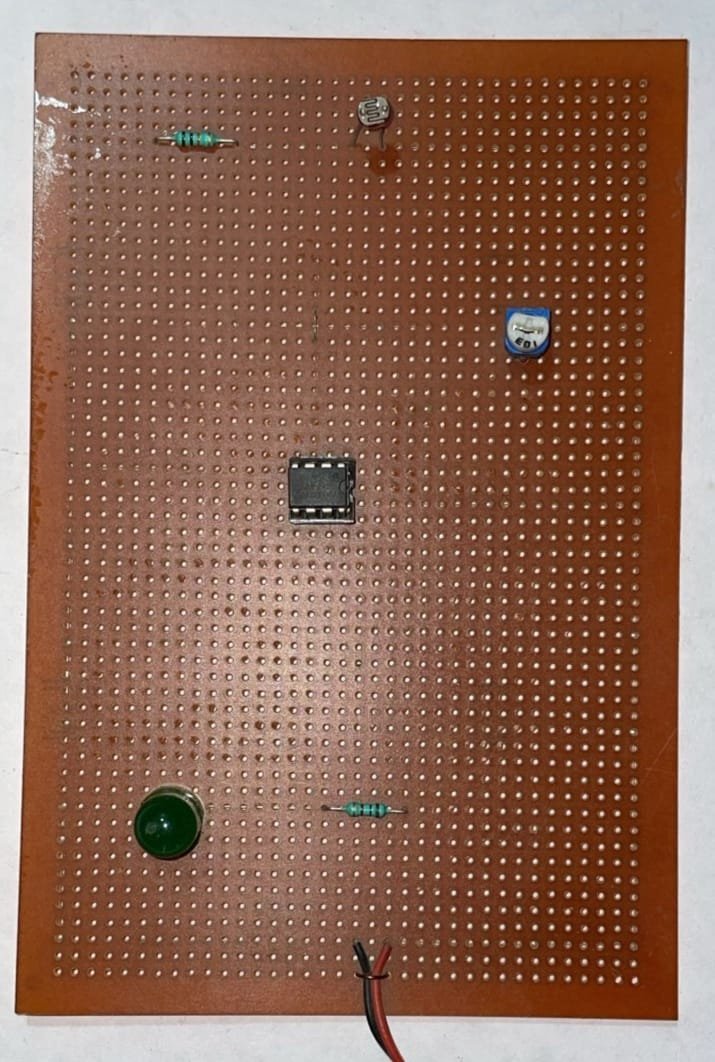
The Dark Sensor using an LDR (Light Dependent Resistor) detects low light conditions to trigger an output action, such as turning on an LED or activating a relay. The LDR changes resistance based on ambient light levels, which is used to control the circuit, making it ideal for automatic lighting systems and light-sensitive applications.
₹295.00 ₹531.00 (Incl. GST)
4 in stock
Dark Sensor Using LDR
A Dark Sensor circuit is designed to detect low light conditions and can be used in various applications like automatic lighting systems or night-activated devices. This project utilizes a Light Dependent Resistor (LDR), which changes its resistance based on the light intensity, to control a switching mechanism or activate an output when darkness is detected.
Components Needed
- LDR (Light Dependent Resistor): A light-sensitive resistor whose resistance varies with the amount of light falling on it.
- Transistor: To act as a switch (e.g., BC547 or similar).
- Resistor: To create a voltage divider with the LDR (e.g., 10kΩ).
- Relay or LED: As the output device to indicate dark conditions or control a load.
- Capacitor: Optional, for stabilization and filtering.
- PCB (Printed Circuit Board): For assembling the circuit in a compact and durable format.
- Power Supply: Typically 5V DC for powering the circuit.
How It Works
The LDR is placed in a voltage divider circuit with a fixed resistor. The resistance of the LDR decreases with increasing light intensity and increases when it gets darker. The voltage across the LDR changes accordingly.
- Voltage Divider: The LDR and resistor are connected in series, and the junction between them provides a variable voltage that changes with light intensity.
- Transistor Switch: This voltage is fed into the base of a transistor. When the light level falls below a certain threshold (i.e., the ambient light decreases), the transistor turns on, activating the relay or LED.
In practical use, the LDR and fixed resistor values are selected so that the transistor switches on at the desired darkness level. The output can then control a relay to switch on a lamp or other device, or directly drive an LED to signal the dark condition.
Assembly
Assemble the components on a PCB, ensuring correct placement and connections. Connect the LDR and resistor to form the voltage divider, and interface this with the transistor. The output of the transistor can be connected to a relay or LED, depending on the application.
The Dark Sensor Using LDR provides a simple yet effective method to detect and respond to low light conditions, making it ideal for creating automated lighting systems and other light-sensitive applications.
| Weight | 0.00 kg |
|---|---|
| Dimensions | 0.00 × 0.00 × 0.00 cm |


