Projects
Showing 25–48 of 59 resultsSorted by popularity
-
B.Tech Diploma Mini Projects
Transistor as Switch
Click Here to Download the Circuit Diagram of “Transistor as Switch”
The Transistor as a Switch project demonstrates how a transistor can control a high-current load with a low-current signal. In this setup, the transistor acts as an electronic switch, using its ability to amplify current to turn a load on or off.
Components:
- NPN Transistor (e.g., BC547)
- Resistor (base resistor)
- Load (e.g., LED with current-limiting resistor)
- Power Supply
Working:
- Base Resistor: Connects the transistor’s base to a control signal (e.g., a microcontroller or a switch). This resistor limits the base current.
- Collector-Emitter Path: The load is connected between the collector of the transistor and the power supply. When the transistor is in the “on” state (saturated), current flows from the collector to the emitter, powering the load.
- Control Signal: Applying a small voltage to the base allows a larger current to flow from the collector to the emitter, thus switching the load on.
When the control signal is high, the transistor conducts, and the load is energized. When the control signal is low, the transistor stops conducting, and the load turns off. This simple yet effective project showcases the transistor’s utility in switching applications.
SKU: transistor-as-switch-project -
Robot Projects
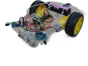
Obstacle Avoidance Robot Car using IR Sensor
https://computronicslab.com/wp-content/uploads/2025/03/Obstacle-Avoidance-Robot-Car-using-IR-Sensor.mp4The Obstacle Avoidance Robot Car using IR Sensors is an autonomous vehicle that detects and avoids obstacles in its path. It is ideal for students, hobbyists, and robotics enthusiasts looking to learn about sensor-based navigation.
How It Works:
The robot uses Infrared (IR) sensors to detect obstacles by emitting and receiving infrared signals. When an obstacle is detected, the motor driver changes the direction of the wheels to avoid collisions, allowing smooth autonomous movement.
Key Components:
- IR Sensors for obstacle detection.
- Motor Driver Module to control movement.
- DC Motors & Wheels for navigation.
- Chassis & Battery for stability and power.
Applications & Benefits:
- Hands-free navigation without human control.
- Educational project for learning robotics.
- Cost-effective and easy to build.
This project provides a practical introduction to robotics, automation, and sensor technology.
SKU: Obstacle Avoidance Robot Car using IR Sensor -
Robot Projects
Surveillance Car using ESP32 Cam module
The Surveillance Car using ESP32 Cam Module project turns a standard remote-controlled car into a mobile surveillance device. The ESP32 Cam module, equipped with a camera, streams live video to a remote server or smartphone, allowing users to monitor the car’s surroundings in real time. The car’s movement and camera angles can be controlled remotely, offering versatility for various applications such as home security or exploration. This project integrates robotics with wireless communication and video streaming, showcasing the ESP32 Cam’s capabilities in creating an advanced, interactive surveillance system. It’s an engaging way to blend electronics, programming, and remote control technologies.
SKU: surveillance-car-using-esp32-cam-module -
STM32 Projects
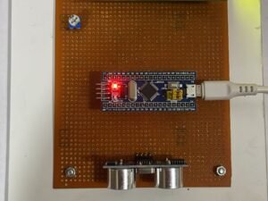
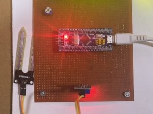
Distance Measurement using Ultrasonic Sensor and STM32
Ultrasonic sensors paired with an STM32 microcontroller provide accurate distance measurements using echolocation. By emitting sound waves and calculating the time for the echo to return, the system determines distances efficiently. This setup is ideal for applications like robotics, parking assistance, and liquid level measurement.
SKU: distance-measurement-using-ultrasonic-sensor-and-stm32 -
B.Tech Diploma Mini Projects
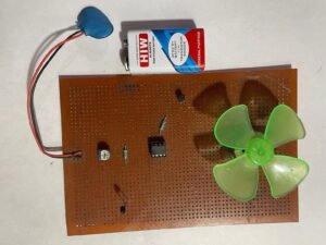
Temperature Controlled DC Fan
A Temperature Controlled DC Fan circuit adjusts fan speed based on temperature variations. Using a temperature sensor and a DC motor driver, it regulates fan operation to maintain a desired temperature. This circuit helps in efficient cooling by automatically increasing or decreasing fan speed as temperature changes, enhancing energy efficiency.SKU: temperature-controlled-dc-fan-project -
B.Tech Diploma Mini Projects
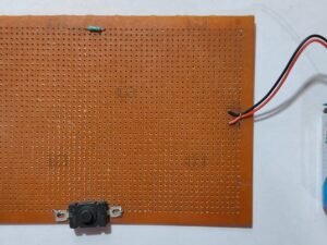
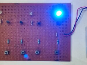
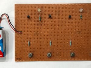
Simple Led On Off Circuit
A Simple LED On/Off Circuit is a basic electronic circuit designed to control the state of an LED (Light Emitting Diode) using a switch. It typically consists of an LED, a resistor, a switch, and a power source. The resistor limits the current flowing through the LED to prevent damage. When the switch is closed, current flows through the circuit, causing the LED to light up. When the switch is open, the circuit is broken, and the LED turns off. This straightforward circuit is often used for learning and testing purposes, as well as in various simple electronic projects.
SKU: simple-led-on-off-circuit-project -
B.Tech Diploma Mini Projects
NAND Gate
Click Here to Download the Circuit Diagram of “NAND Gate”
Discover how a NAND gate operates, a fundamental digital logic gate crucial for building complex circuits and performing binary operations.
SKU: nand-gate-mini-project -
B.Tech Diploma Mini Projects
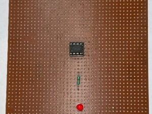
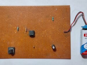
Astable Multivibrator using IC555
The Astable Multivibrator using IC 555 creates a continuous square wave output, functioning as an oscillator. Configured with resistors and capacitors, the 555 timer generates a periodic signal used for applications like blinking LEDs or generating clock pulses. This project demonstrates the timer’s capability to produce adjustable frequency waveforms.
SKU: astable-multivibrator-using-ic555-project -
B.Tech Diploma Mini Projects
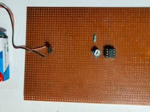
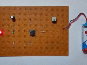
Temperature Indicator using LM35 and IC741
The Temperature Indicator using LM35 and IC741 project measures and displays temperature values. The LM35 temperature sensor provides an analog voltage proportional to the temperature, which is fed into the IC741 operational amplifier. The IC741 amplifies and processes the voltage signal, allowing it to be read on a display or analog meter. This project demonstrates analog temperature measurement and signal conditioning using commonly available electronic components.
SKU: temperature-indicator-using-lm35-and-ic741-project -
Robot Projects
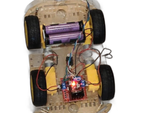
Rf Control Robot using RF Module
This project focuses on building an RF-controlled robot using an RF transmitter and receiver module for wireless communication. The robot can be remotely operated using radio frequency (RF) signals, making it ideal for surveillance, remote monitoring, and automation applications.
Working Principle:
- The RF transmitter sends control signals using push buttons.
- The RF receiver receives these signals and decodes them using a decoder IC (HT12D).
- The decoded signals control motor driver IC (L298N or L293D), which drives the robot’s motors accordingly.
Applications & Benefits:
- Used in wireless robotic applications such as remote-controlled cars, industrial automation, and military surveillance.
- Provides long-range communication (typically up to 100 meters).
- Simple and cost-effective project for learning RF communication and robotics.
SKU: Rf Control Robot using RF Module (without Microcontroller) -
STM32 Projects
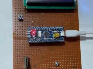
Wireless Notice Board using STM32
A Wireless Notice Board using an STM32 microcontroller, an LCD, and Bluetooth allows for dynamic message updates. Users can send messages wirelessly via Bluetooth, which the STM32 processes and displays on the LCD. This system is ideal for real-time updates in schools, offices, or public spaces.
SKU: Wireless Notice Board using STM32 -
Robot Projects
Line Following Robot (LFR) Car using Arduino Uno
The Line Following Robot Car using Arduino Uno autonomously follows a predefined path using infrared sensors. The Arduino Uno processes sensor data to detect the line and adjusts the car’s direction to stay on track. This project is perfect for learning about robotics, sensor integration, and control systems.
SKU: line-following-robot-car-using-arduino-uno -
Robot Projects
Bluetooth Voice Control Robot Car using Arduino
The Bluetooth Voice Control Robot Car using Arduino allows users to control a robot car via voice commands transmitted through a Bluetooth connection. The Arduino processes voice commands received from a smartphone app to maneuver the car. Ideal for remote-controlled projects and interactive robotics.SKU: bluetooth-remote-control-car-using-arduino-1 -
Robot Projects
Bluetooth Remote Control Robot Car using Arduino
The Bluetooth Remote Control Robot Car using Arduino is an exciting project that combines robotics and wireless communication. This DIY kit allows you to build a robot car that can be controlled remotely via Bluetooth. Utilizing an Arduino board as the controller, this project integrates a Bluetooth module for wireless communication, enabling you to steer and operate the car from your smartphone or tablet. The robot car typically features motors for movement, a motor driver to control the motors, and various sensors for obstacle detection. Ideal for electronics enthusiasts, this project offers hands-on experience with Arduino programming and Bluetooth technology.
SKU: bluetooth-remote-control-car-using-arduino -
STM32 Projects
Soil Moisture Percentage Measurement using STM32
Using an STM32 microcontroller, soil moisture measurement can be efficiently achieved. Connect a soil moisture sensor to the STM32’s ADC input, read the analog value, convert it to voltage, and map it to a moisture percentage. This system helps automate irrigation, ensuring optimal water usage and healthy crop growth.
SKU: Soil Moisture Percentage Measurement using STM32 -
B.Tech Diploma Mini Projects
Monostable Multivibrator with IC 555 Timer Circuit
A Monostable Multivibrator circuit using the IC 555 timer generates a single pulse of fixed duration in response to an input trigger. It converts a short input pulse into a longer output pulse, making it ideal for timing applications, pulse width modulation, and creating time delays in electronic circuits.
SKU: monostable-multivibrator-with-ic-555-timer-circuit-project -
B.Tech Diploma Mini Projects
Blinking LED using IC555
Click Here to Download the Circuit Diagram of “Blinking LED using IC 555”
The Blinking LED using IC 555 project creates a flashing LED effect by configuring the 555 timer in astable mode. The timer generates a continuous square wave signal, causing the LED to blink at a rate determined by external resistors and capacitors, providing a simple demonstration of timing and pulse generation.
SKU: blinking-led-using-ic555-project -
B.Tech Diploma Mini Projects
Flashing LED using IC 555
Flashing LED using IC 555 is a beginner-friendly project showcasing the 555 timer’s astable mode. It alternates LED states between on and off using resistors, capacitors, and the timer’s configuration, making it ideal for learning basic electronics and LED control concepts.
SKU: flashing-led-using-ic-555 -
B.Tech Diploma Mini Projects
Simple Transistor Tester
Click Here to Download the Circuit Diagram of “Transistor Tester”
A Transistor Tester is an essential electronic device used to evaluate the functionality of transistors. It can identify transistor types (NPN or PNP), measure their gain (hFE), and test their various pins to ensure proper connections. The tester typically features an easy-to-read display and controls that allow users to input the transistor’s pins for measurement. By applying a small test current, the device checks the transistor’s switching and amplification properties, providing valuable information about its health and performance. This tool is crucial for electronics enthusiasts and technicians for diagnosing and repairing electronic circuits.
SKU: transistor-tester-project -
B.Tech Diploma Mini Projects
NAND NOR Gate
Click Here to Download the Circuit Diagram of “NAND NOR Gate”
The NAND NOR Gate project explores the fundamental building blocks of digital logic circuits. By constructing and testing NAND and NOR gates using logic ICs or discrete components, this project demonstrates how these gates perform basic logical operations. The NAND gate outputs true only when not all inputs are true, while the NOR gate outputs true only when all inputs are false. The project involves wiring the gates in a breadboard circuit and verifying their functionality with various input combinations. This practical exercise provides insights into how these gates are used to create complex digital systems and perform logical decision-making tasks.
SKU: nand-nor-gate-project -
B.Tech Diploma Mini Projects
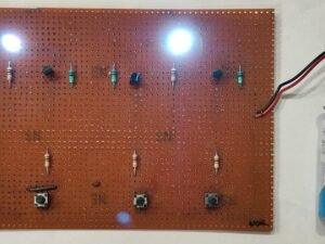
AND OR NOT Gate
Click Here to Download the Circuit Diagram of “AND OR NOT Gate”
The <strong>AND OR NOT Gate project focuses on understanding and implementing fundamental logic gates: AND, OR, and NOT. The AND gate outputs true only when all its inputs are true, the OR gate outputs true if at least one input is true, and the NOT gate inverts the input signal. By building circuits with these gates using ICs or discrete components, you can observe how they combine to perform various logical operations. This project involves designing and testing circuits on a breadboard, verifying their behavior with different input combinations. It’s an essential exercise for grasping the basics of digital logic and circuit design.
SKU: and-or-not-gate-project -
B.Tech Diploma Mini Projects
AND OR Gate
Click Here to Download the Circuit Diagram of “AND OR Gate”
The AND OR Gate project explores two fundamental logic gates: the AND gate and the OR gate.
- AND Gate: Outputs true only when all its inputs are true. For example, with two inputs, the output is high (1) only if both inputs are high (1).
- OR Gate: Outputs true if at least one of its inputs is true. For instance, with two inputs, the output is high (1) if either input is high (1), or both are high.
In this project, you’ll construct circuits using these gates to understand their behavior and interactions. By experimenting with different input combinations and observing the outputs, you’ll gain insights into basic digital logic and how these gates can be combined to form complex logic functions.
SKU: and-or-gate-project -
B.Tech Diploma Mini Projects
Diode as a Switch
Click Here to Download the Circuit Diagram of “Diode as a Switch”
The Diode as a Switch project demonstrates how a diode can be used to control the flow of current in a circuit, functioning similarly to a switch. This project illustrates the diode’s fundamental role in electronics, showcasing its ability to permit current flow in one direction while blocking it in the reverse direction.SKU: diode-as-a-switch-mini-project