
DC Motor Speed and Direction Control
1 in stock
DC Motor Speed and Direction Control
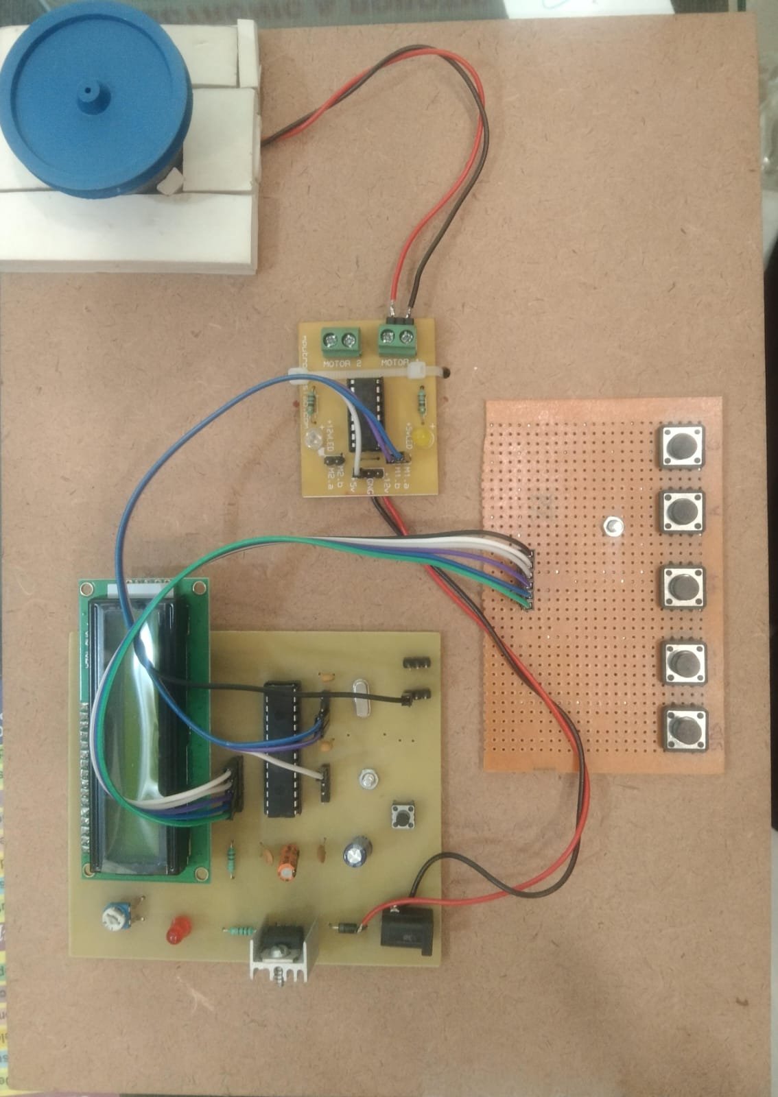
Controlling the speed and direction of a DC motor is essential in robotics, automation, and various electronic systems. This project demonstrates how to control a DC motor’s speed and direction using a microcontroller (like Arduino), an H-bridge motor driver (such as L298N or L293D), and PWM (Pulse Width Modulation).
₹3,481.00 ₹4,130.00 (Incl. GST)
1 in stock
DC Motor Speed and Direction Control
Controlling the speed and direction of a DC motor is essential in robotics, automation, and various electronic systems. This project demonstrates how to control a DC motor’s speed and direction using a microcontroller (like Arduino), an H-bridge motor driver (such as L298N or L293D), and PWM (Pulse Width Modulation).
⚙️ Working Principle
-
Speed Control using PWM:
-
PWM is a technique used to vary the average voltage supplied to the motor by switching it ON and OFF rapidly.
-
The higher the duty cycle (ON time), the faster the motor rotates.
-
Arduino can generate PWM signals using the
analogWrite()function.
-
-
Direction Control using H-Bridge:
-
An H-bridge is an electronic circuit that allows voltage to be applied across a load in either direction.
-
It consists of 5 switches/transistors; by changing their states, the current flow through the motor can be reversed.
-
L298N and L293D motor drivers make this easy by providing input pins to control direction and enable pins for speed control.
Typical Connections:
-
IN1 and IN2 control direction (e.g., IN1 HIGH & IN2 LOW = Forward)
-
ENA (Enable pin) controls speed using PWM
-
Arduino takes user input (e.g., from a potentiometer or buttons) and adjusts motor behavior accordingly
💡 Applications:
-
Robotics (line follower, obstacle avoidance)
-
Conveyor belts
-
Smart home devices (curtains, fans)
-
Electric vehicles
✅ Advantages:
-
Precise control over motion
-
Easily programmable and scalable
-
Can be expanded for dual motors or remote control
-
-
Related products
-
B.Tech Diploma Mini Projects
Astable Multivibrator using IC555
The Astable Multivibrator using IC 555 creates a continuous square wave output, functioning as an oscillator. Configured with resistors and capacitors, the 555 timer generates a periodic signal used for applications like blinking LEDs or generating clock pulses. This project demonstrates the timer’s capability to produce adjustable frequency waveforms.
SKU: astable-multivibrator-using-ic555-project -
B.Tech Diploma Mini Projects
Dark Sensor Using LDR
Click Here to Download the Circuit Diagram of “Dark Sensor Using LDR”
The Dark Sensor using an LDR (Light Dependent Resistor) detects low light conditions to trigger an output action, such as turning on an LED or activating a relay. The LDR changes resistance based on ambient light levels, which is used to control the circuit, making it ideal for automatic lighting systems and light-sensitive applications.
SKU: dark-sensor-project -