
Flashing LED using IC 555
6 in stock
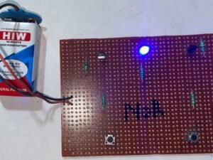
Flashing LED using IC 555 is a beginner-friendly project showcasing the 555 timer’s astable mode. It alternates LED states between on and off using resistors, capacitors, and the timer’s configuration, making it ideal for learning basic electronics and LED control concepts.
₹295.00 ₹519.20 (Incl. GST)
6 in stock
Flashing LED using IC 555
Flashing LED using IC 555 is a popular electronics project that utilizes the 555 timer IC (integrated circuit) in its astable mode configuration. This setup allows the LED to continuously blink or flash at a specific rate, determined by the values of external resistors and capacitors connected to the 555 timer.
Project Overview
The 555 timer IC is versatile and widely used in various timer, oscillator, and pulse generation applications. In the astable mode, it functions as an oscillator, generating a continuous square wave output. This output is then used to drive an LED, causing it to blink on and off.
Components Needed
To build a basic Flashing LED circuit using IC 555, you will typically need the following components:
- 555 Timer IC: The heart of the circuit that generates the oscillating signal.
- Resistors: Two resistors (R1 and R2) to set the frequency of the blinking LED.
- Capacitor: A capacitor (C) to control the timing of the oscillation.
- LED: The light-emitting diode that blinks on and off.
- Power Supply: Usually a 5V or 9V DC power source, depending on the specifications of the components used.
Circuit Design
- 555 Timer Connections:
- Pin 1 (Ground): Connected to the ground of the power supply.
- Pin 8 (VCC): Connected to the positive terminal of the power supply.
- Pin 4 (Reset): Usually connected to VCC to prevent accidental resets.
- Pin 5 (Control Voltage): Not used in astable mode.
- Pins 2 (Trigger) and 6 (Threshold): Connected through resistors and capacitor to control the timing of the oscillator.
- Astable Mode Configuration:
- In this mode, Pins 2 and 6 are connected together and to the capacitor (C).
- Pin 2 (Trigger) is connected through a resistor (R1) to Pin 7 (Discharge).
- Pin 7 is also connected to Pin 6 through another resistor (R2).
- Pin 3 (Output) drives the LED through a current-limiting resistor.
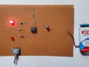
- Operation:
- When powered, the capacitor charges and discharges through R1 and R2, causing Pin 3 to oscillate between high and low states.
- This oscillation toggles the LED on and off, creating a flashing effect.
Applications
Flashing LED circuits using IC 555 are used in various applications such as:
- Visual Indicators: Used to indicate operation or status in electronic devices.
- Decorative Lighting: Creating blinking effects in displays and decorations.
- Educational Purposes: Learning about timers, oscillators, and basic electronic components.
Conclusion
The Flashing LED using IC 555 project is an excellent introduction to practical electronics and the versatile applications of the 555 timer IC. It teaches fundamental concepts such as timing circuits, oscillators, and LED control, making it a popular choice among hobbyists, students, and electronics enthusiasts alike.
| Weight | 0.00 kg |
|---|---|
| Dimensions | 0.00 × 0.00 × 0.00 cm |
Related products
-
B.Tech Diploma Mini Projects
IR Remote Control LED ON OFF
The IR Remote Control LED ON/OFF project uses an infrared (IR) receiver and a remote control to toggle an LED’s state. The IR receiver detects signals from the remote, which are then processed to turn the LED on or off. This project demonstrates basic remote control functionality and IR signal reception in electronics.
SKU: ir-remote-control-led-on-off-project -
-
B.Tech Diploma Mini Projects
Bike Turning Indicator
The Bike Turning Indicator project provides visual signals for turning or lane changes on a bicycle. Using LEDs and a switch or relay, the system activates a set of blinking lights on the bike to signal turns or lane changes to other road users. This project enhances safety and visibility for cyclists by implementing a simple electronic control system for indicator lights.
SKU: bike-turning-indicator-project