IC 555 – Timer IC (Pack of 5)
1 in stock
₹45.84 ₹94.40 (Incl. GST)
1 in stock
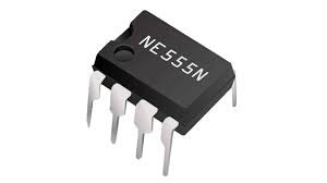
IC 555 – Timer IC
Overview
The IC 555 is one of the most popular and versatile integrated circuits used in electronics. It is widely used for its capability to operate in various modes, including timer, pulse generator, and oscillator. Designed by Hans R. Camenzind in 1972, the 555 timer IC remains a fundamental component in both educational and professional electronic designs.
Features
- Versatile Operation: Can be configured as a monostable (one-shot), astable (oscillator), or bistable (flip-flop) multivibrator.
- Precision Timing: Provides accurate time delays and oscillations with minimal external components.
- Wide Voltage Range: Operates over a broad voltage range, typically from 4.5V to 15V.
- Stable Performance: Offers stable performance with low drift and high reliability.
- Low Power Consumption: Designed to consume minimal power, making it suitable for battery-powered devices.
- High Output Current: Can drive loads directly with output currents up to 200mA.
Pin Configuration
The IC 555 is available in an 8-pin Dual In-line Package (DIP) with the following pin configuration:
- Pin 1: GND – Ground connection.
- Pin 2: TRIG – Trigger input for initiating the timing cycle in monostable mode.
- Pin 3: OUT – Output pin that provides the timing signal or pulse.
- Pin 4: RESET – Active-low reset pin used to terminate the timing cycle.
- Pin 5: CTRL – Control voltage input for adjusting the timing cycle (typically connected to a capacitor for stability).
- Pin 6: THRS – Threshold input for terminating the timing cycle in monostable mode.
- Pin 7: DISCH – Discharge pin for discharging the timing capacitor.
- Pin 8: VCC – Supply voltage pin.
Working Principle
- Monostable Mode: In this mode, the 555 operates as a one-shot timer. It generates a single pulse of a specific width in response to a trigger input. The pulse width is determined by an external resistor and capacitor.
- Astable Mode: The 555 operates as an oscillator, generating a continuous square wave output. The frequency and duty cycle of the output waveform are determined by external resistors and capacitors.
- Bistable Mode: The 555 functions as a flip-flop, toggling its output state between high and low in response to external trigger signals. It can be used for simple on/off switching applications.
Applications
- Timing Delays: Used in applications requiring precise timing delays, such as in delay timers and pulse generators.
- Oscillators: Functions as a clock oscillator in various circuits, including waveform generators and frequency dividers.
- Pulse Width Modulation: Employed in PWM circuits for motor control, light dimming, and signal modulation.
- Tone Generators: Generates audio tones for alarms, buzzers, and sound effects.
- Flashing Lights: Creates flashing light effects in decorative and signaling applications.
Example Circuits
- Monostable Timer: Connect a resistor and capacitor to Pins 6 and 7. Trigger the timing cycle by applying a low pulse to Pin 2, and the output pulse can be read from Pin 3.
- Astable Oscillator: Connect two resistors and a capacitor to Pins 6 and 7. The output frequency and duty cycle are determined by these components, and the continuous square wave is available at Pin 3.
Advantages
- Ease of Use: Simple to configure with minimal external components, making it ideal for beginners and experienced engineers alike.
- Flexibility: Can be used in various modes for different applications, offering a high degree of versatility.
- Cost-Effective: Widely available and inexpensive, making it a popular choice for many electronic projects.
Conclusion
The IC 555 is a fundamental component in electronics, offering versatility, precision, and ease of use. Whether used as a timer, oscillator, or flip-flop, it provides reliable performance and is suitable for a wide range of applications. Its enduring popularity is a testament to its effectiveness and simplicity in electronic design.
You may also like…
-
B.Tech Diploma Mini Projects
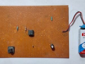
Monostable Multivibrator with IC 555 Timer Circuit
A Monostable Multivibrator circuit using the IC 555 timer generates a single pulse of fixed duration in response to an input trigger. It converts a short input pulse into a longer output pulse, making it ideal for timing applications, pulse width modulation, and creating time delays in electronic circuits.
SKU: monostable-multivibrator-with-ic-555-timer-circuit-project -
DC Motors
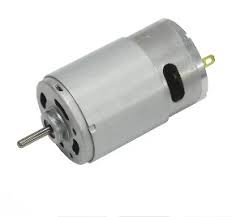
555 DC Motor 12V
The 555 DC Motor 12V is a high-torque, durable motor perfect for various applications. Operating on a 12V DC power supply, it provides reliable performance for robotics, automotive systems, and DIY projects. Its compact design fits into tight spaces, while its robust construction ensures long-term durability and efficiency, making it an excellent choice for powering machinery and diverse mechanical tasks.
SKU: 555-dc-motor-12v -
B.Tech Diploma Mini Projects
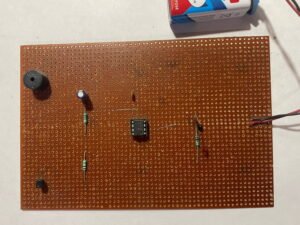
Fire Alarm Using Thermistor and IC 555
The Fire Alarm using a Thermistor detects temperature changes. As heat rises, the thermistor’s resistance drops, triggering the alarm. It’s a simple, cost-effective way to enhance safety in homes and offices by providing early warnings of potential fire hazards.
SKU: fire-alarm-using-thermistor-project

