B.Tech Diploma Mini Projects
Showing 25–45 of 45 resultsSorted by popularity
-
B.Tech Diploma Mini Projects
Astable Multivibrator using IC555
The Astable Multivibrator using IC 555 creates a continuous square wave output, functioning as an oscillator. Configured with resistors and capacitors, the 555 timer generates a periodic signal used for applications like blinking LEDs or generating clock pulses. This project demonstrates the timer’s capability to produce adjustable frequency waveforms.
SKU: astable-multivibrator-using-ic555-project -
B.Tech Diploma Mini Projects
Temperature Indicator using LM35 and IC741
The Temperature Indicator using LM35 and IC741 project measures and displays temperature values. The LM35 temperature sensor provides an analog voltage proportional to the temperature, which is fed into the IC741 operational amplifier. The IC741 amplifies and processes the voltage signal, allowing it to be read on a display or analog meter. This project demonstrates analog temperature measurement and signal conditioning using commonly available electronic components.
SKU: temperature-indicator-using-lm35-and-ic741-project -
B.Tech Diploma Mini Projects
Monostable Multivibrator with IC 555 Timer Circuit
A Monostable Multivibrator circuit using the IC 555 timer generates a single pulse of fixed duration in response to an input trigger. It converts a short input pulse into a longer output pulse, making it ideal for timing applications, pulse width modulation, and creating time delays in electronic circuits.
SKU: monostable-multivibrator-with-ic-555-timer-circuit-project -
B.Tech Diploma Mini Projects
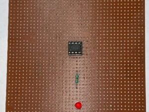
Blinking LED using IC555
Click Here to Download the Circuit Diagram of “Blinking LED using IC 555”
The Blinking LED using IC 555 project creates a flashing LED effect by configuring the 555 timer in astable mode. The timer generates a continuous square wave signal, causing the LED to blink at a rate determined by external resistors and capacitors, providing a simple demonstration of timing and pulse generation.
SKU: blinking-led-using-ic555-project -
B.Tech Diploma Mini Projects
Flashing LED using IC 555
Flashing LED using IC 555 is a beginner-friendly project showcasing the 555 timer’s astable mode. It alternates LED states between on and off using resistors, capacitors, and the timer’s configuration, making it ideal for learning basic electronics and LED control concepts.
SKU: flashing-led-using-ic-555 -
B.Tech Diploma Mini Projects
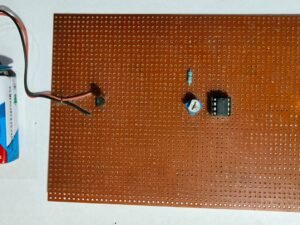
Simple Transistor Tester
Click Here to Download the Circuit Diagram of “Transistor Tester”
A Transistor Tester is an essential electronic device used to evaluate the functionality of transistors. It can identify transistor types (NPN or PNP), measure their gain (hFE), and test their various pins to ensure proper connections. The tester typically features an easy-to-read display and controls that allow users to input the transistor’s pins for measurement. By applying a small test current, the device checks the transistor’s switching and amplification properties, providing valuable information about its health and performance. This tool is crucial for electronics enthusiasts and technicians for diagnosing and repairing electronic circuits.
SKU: transistor-tester-project -
B.Tech Diploma Mini Projects
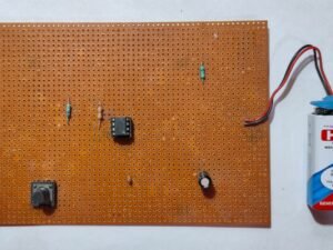
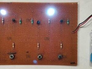
NAND NOR Gate
Click Here to Download the Circuit Diagram of “NAND NOR Gate”
The NAND NOR Gate project explores the fundamental building blocks of digital logic circuits. By constructing and testing NAND and NOR gates using logic ICs or discrete components, this project demonstrates how these gates perform basic logical operations. The NAND gate outputs true only when not all inputs are true, while the NOR gate outputs true only when all inputs are false. The project involves wiring the gates in a breadboard circuit and verifying their functionality with various input combinations. This practical exercise provides insights into how these gates are used to create complex digital systems and perform logical decision-making tasks.
SKU: nand-nor-gate-project -
B.Tech Diploma Mini Projects
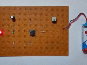
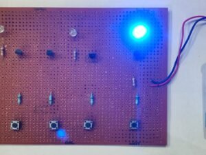
AND OR NOT Gate
Click Here to Download the Circuit Diagram of “AND OR NOT Gate”
The <strong>AND OR NOT Gate project focuses on understanding and implementing fundamental logic gates: AND, OR, and NOT. The AND gate outputs true only when all its inputs are true, the OR gate outputs true if at least one input is true, and the NOT gate inverts the input signal. By building circuits with these gates using ICs or discrete components, you can observe how they combine to perform various logical operations. This project involves designing and testing circuits on a breadboard, verifying their behavior with different input combinations. It’s an essential exercise for grasping the basics of digital logic and circuit design.
SKU: and-or-not-gate-project -
B.Tech Diploma Mini Projects
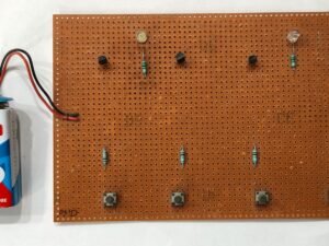
AND OR Gate
Click Here to Download the Circuit Diagram of “AND OR Gate”
The AND OR Gate project explores two fundamental logic gates: the AND gate and the OR gate.
- AND Gate: Outputs true only when all its inputs are true. For example, with two inputs, the output is high (1) only if both inputs are high (1).
- OR Gate: Outputs true if at least one of its inputs is true. For instance, with two inputs, the output is high (1) if either input is high (1), or both are high.
In this project, you’ll construct circuits using these gates to understand their behavior and interactions. By experimenting with different input combinations and observing the outputs, you’ll gain insights into basic digital logic and how these gates can be combined to form complex logic functions.
SKU: and-or-gate-project -
B.Tech Diploma Mini Projects
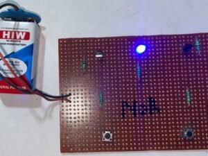
Diode as a Switch
Click Here to Download the Circuit Diagram of “Diode as a Switch”
The Diode as a Switch project demonstrates how a diode can be used to control the flow of current in a circuit, functioning similarly to a switch. This project illustrates the diode’s fundamental role in electronics, showcasing its ability to permit current flow in one direction while blocking it in the reverse direction.SKU: diode-as-a-switch-mini-project -
-
-
B.Tech Diploma Mini Projects
Electronic Letter Box using IC 555
The Electronic Letter Box project automates mail detection and notification. It typically uses sensors (like infrared or magnetic) to detect when the letter box door is opened or when mail is inserted. The system can activate an alert, such as a buzzer or LED, to notify the owner of new mail. This project integrates sensor technology with electronic signaling to improve mail management and security.
SKU: electronic-letter-box-project -
B.Tech Diploma Mini Projects
IR Remote Tester
The IR Remote Tester project verifies the functionality of an infrared (IR) remote control. By using an IR receiver and a display or LED, this circuit detects and displays signals from the remote. When a button is pressed, the tester shows whether the remote is transmitting a signal, helping diagnose remote control issues.
SKU: ir-remote-tester-project -
B.Tech Diploma Mini Projects
Bike Turning Indicator
The Bike Turning Indicator project provides visual signals for turning or lane changes on a bicycle. Using LEDs and a switch or relay, the system activates a set of blinking lights on the bike to signal turns or lane changes to other road users. This project enhances safety and visibility for cyclists by implementing a simple electronic control system for indicator lights.
SKU: bike-turning-indicator-project -
B.Tech Diploma Mini Projects
IR Remote Control LED ON OFF
The IR Remote Control LED ON/OFF project uses an infrared (IR) receiver and a remote control to toggle an LED’s state. The IR receiver detects signals from the remote, which are then processed to turn the LED on or off. This project demonstrates basic remote control functionality and IR signal reception in electronics.
SKU: ir-remote-control-led-on-off-project -
B.Tech Diploma Mini Projects
Binary Encoder
The Binary Encoder project converts decimal inputs into binary outputs. Using a set of switches or inputs, the encoder generates a binary code corresponding to the active input. This binary code is then displayed or processed by digital systems. This project showcases basic digital encoding principles, demonstrating how to translate multiple input states into a binary format.
SKU: binary-encoder-project -
B.Tech Diploma Mini Projects
LED Chaser
The LED Chaser project creates a visual effect where LEDs light up in a sequential pattern, resembling a moving wave or “chase.” Using a 555 timer IC or a dedicated LED chaser IC, the circuit generates a timed sequence that activates LEDs one by one. This project is popular for creating dynamic light displays and demonstrates basic sequential logic and timing in electronics.
SKU: led-chaser-project -
B.Tech Diploma Mini Projects
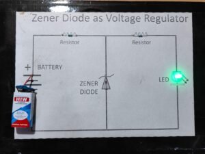
Zener Diode as Voltage Regulator
Click Here to Download the Circuit Diagram of “Zener Diode as Voltage Regulator”
The Zener Diode as a Voltage Regulator project involves using a Zener diode to maintain a stable output voltage across varying input voltages. The Zener diode operates in reverse breakdown mode, where it maintains a constant voltage (the Zener voltage) regardless of changes in input voltage or load conditions.
In this project, a Zener diode is connected in reverse bias across a load resistor. When the input voltage exceeds the Zener voltage, the diode starts conducting and clamps the output voltage to the Zener voltage. This configuration ensures a stable and regulated output voltage, making it ideal for powering sensitive electronic circuits. Proper heat dissipation and current limiting resistors are essential for optimal performance and reliability.
SKU: zener-diode-as-voltage-regulator-project